eccRATERS. coM


RESIDENTIAL
-
Are you are considering a new construction project?
We can help! Hiring an ECC/HERS Rater early in the project will help each stage come together.
Do you need a contractor?
Do you need an energy consultant?
Have you already started a project?
Make an appointment for a free phone consultation.We can evaluate your CF1R and identify any potential issues, and rectify them before they cause delays. Set up a free phone consultation.
-
It is important to hire an ECC/HERS Rater early to address any potential issues that may have been over-looked on. your compliance certificates. Call for a free phone consultation
-
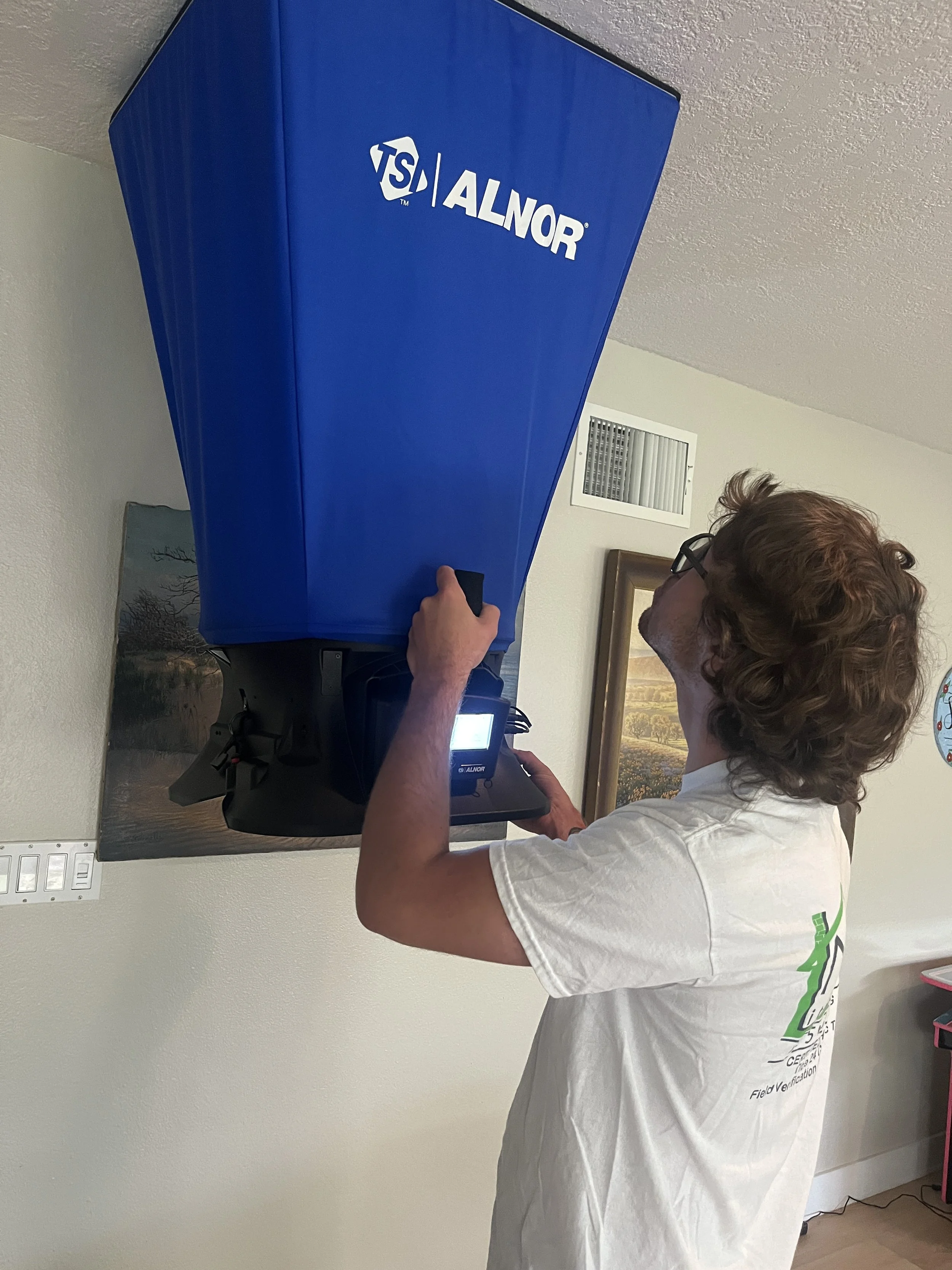
Diagnostic Testing and Field Verification Required By the California Energy Commission-tests vary based on location and equipment installed
-
Quality Insulation Inspection.
Consists of three separate inspections
Airseal-must me completed at rough-in before insulation is installed
Insulation-during or immediately after insulation install
Final airseal-done during drywall
-
We can pull your permit, complete ECC/HER verification, schedule final inspection, meet the inspector and facilitate any remediation necessary.
Our Services
ECC Title 24 Diagnostic Testing & Field Verification
Diagnostic Testing and Field Verification Required By the California Energy Commission:
Variable Capacity Systems, ie mini-splits, most side discharge systems.
Traditional split systems and package units.
Ducts in Conditioned Space Verification-See Residential Appendices: RA3.1.4.1.3 for definition
Duct Leakage
Quality Insulation Installation Inspection. Seen as QII on your CF1R
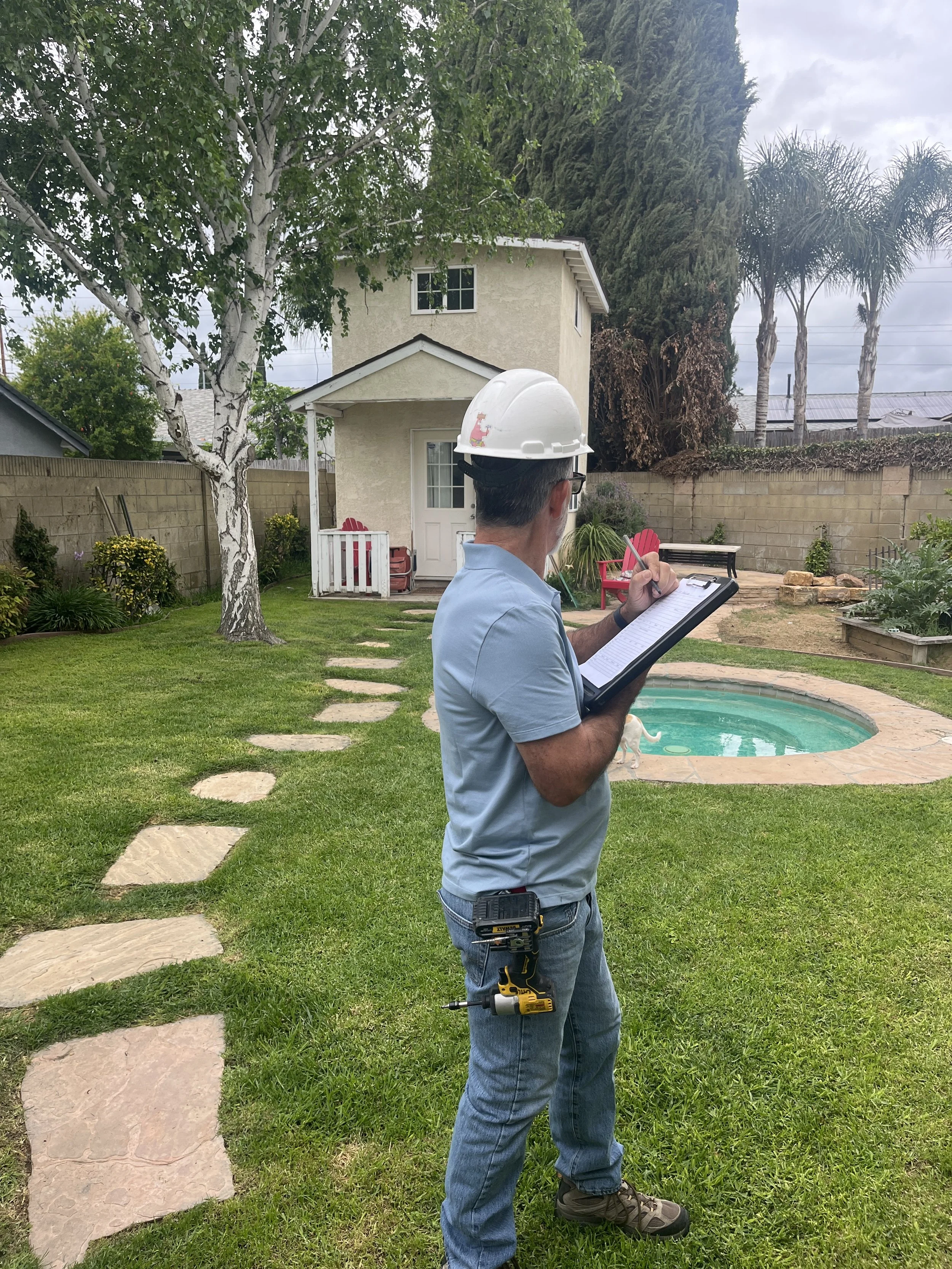
Existing Conditions Inspection
Plumbing-All Lines Insulated
IAQ (Internal Air Quality) Verification for Exhaust and Balanced Sytems
Verified EER/SEER
Kitchen Hood Verification
Building Leakage Diagnostic Testing
Air Balancing System Commissioning Permit Expediting
COMPLIANCE services
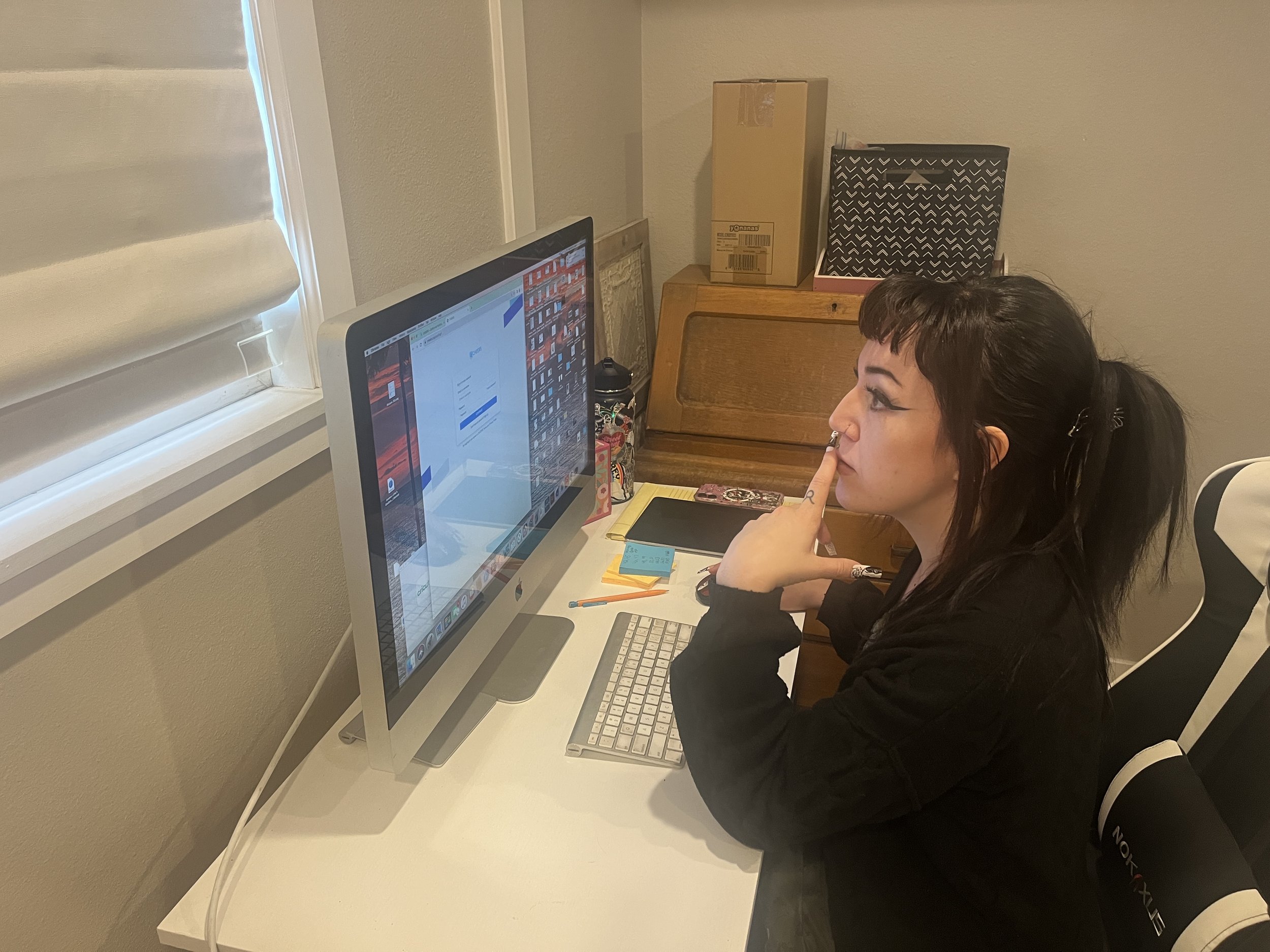
Energy Consultants- Create Compliance Forms
Revision- Interpret and communicate issues with you existing Energy Consultant to resolve discrepancies


Learn about our services
-
Residential Appendices: RA3.1.4.1.3 Visual Verification of Ducts Located Entirely In Conditioned SpaceA visual inspection shall confirm space conditioning duct systems are located entirely in conditioned space. If any part of the space conditioning duct system is outside of conditioned space, the system does not pass.
Section 150.1(c)9. Space conditioning distribution systems.B. Duct and air handlers located in conditioned space. Duct systems and air handlers of HVAC systems shall be located in conditioned space, and confirmed by field verification and diagnostic testing to meet the criterion of Reference Residential Appendix Section RA3.1.4.3.8. Duct insulation levels shall meet the requirements in TABLE 150.1-A.
CONDITIONED SPACE, DIRECTLY is an enclosed space that is provided with wood heating, mechanical heating that has a capacity exceeding 10 Btu/hr-ft², or mechanical cooling that has a capacity exceeding 5 Btu/hr-ft², . Directly conditioned space does not include process space.
-
RA3.1.4.3.1 Diagnostic Duct Leakage from Fan Pressurization of Ducts
The objective of this procedure is for an installer to determine or a rater to verify the total leakage of a new or altered duct system. The total duct leakage shall be determined by pressurizing the entire duct system to a positive pressure of 25 Pa (0.1 inches water) with respect to outside. The following procedure shall be used for the fan pressurization tests:
Verify that the air handler, supply and return plenums and all the connectors, transition pieces, duct boots and registers are installed and sealed. The entire duct system shall be included in the total leakage test.
For newly installed or altered ducts, verify that cloth backed rubber adhesive duct tape has not been used and if a platform or other building cavity used to house the air distribution system has been newly installed or altered, it contains a duct or is ducted with duct board or sheet metal.
Seal all the supply registers and return grilles except for one large centrally located return grille or the air handler cabinet access panel. Floor registers on carpeted floors may be removed and the opening sealed to the floor under the carpet. If allowed by the equipment manufacturer, the air-handling unit blower compartment access panel may be sealed with an approved tape - do not use mastic or other permanent sealing material.
Attach the fan flowmeter device to the duct system at the unsealed return grille or the air handler cabinet access panel. Ensure that the air filter has been removed.
Install a static pressure probe at a supply register located close to the air handler, or at the supply plenum.
Adjust the fan flowmeter to produce a positive 25 Pa (0.1 inches water) pressure at the supply register or the supply plenum with respect to the outside or with respect to the building space with the entry door open to the outside.
Record the flow through the flowmeter; this is the leakage flow at 25 Pa (0.1 inches water).
Divide the leakage flow by the total air handler airflow determined by the procedure in Section RA3.1.4.2 and convert to a percentage. If the leakage flow percentage is equal to or less than the compliance criterion required by the Standards, the system passes.
-
RA3.1.4.2.2 Nominal Air Handler Airflow
Nominal air handler airflow shall be calculated according to one of the following methods as applicable:
For heating-only systems, the nominal air handler airflow shall be 21.7 CFM per kBtu/hr of rated heating output capacity.
For split or packaged cooling systems with only one indoor unit, the nominal air handler airflow shall be 400 CFM per nominal ton of outdoor condensing unit cooling capacity as specified by the manufacturer.
For small duct high velocity systems, the nominal air handler airflow shall be 250 CFM per nominal ton of outdoor condensing unit cooling capacity as specified by the manufacturer.
For multiple-split systems that provide cooling, the nominal air handler airflow for each indoor unit shall be 350 CFM per nominal ton of indoor unit cooling capacity as specified by the manufacturer
-
Refrigeration verifications vary based on the system installed and the climate zone that the projected is located.
Generally, these are the procedures:
For a modulating system, i.e. mini split, or a side-discharged condenser a weigh-in refrigeration verification is required per
RA3.2.3 Weigh-In Charging Procedure
This section specifies the weigh-in charging procedure in which the weight of the required refrigerant charge is determined by using the manufacturer's specifications for a standard refrigerant charge weight and taking into account adjustment factors such as deviations in refrigerant line length and diameter. The calculated weight of refrigerant is then installed using a refrigerant scale. RA3.2.3 provides two procedures: Section RA3.2.3.1 shall be used by the HVAC installer when the weigh-in procedure is required by the Standards for compliance. Section RA3.2.3.2 shall be used by the HERS Rater when the Standards specify use of the procedure for compliance, or specify it as an optional procedure for compliance. The weigh-in charging procedure is an acceptable method for demonstrating compliance at any outdoor temperature, however if the weigh-in charging procedure is used, HERS verification of compliance cannot use group sampling.
HVAC installers shall use the weigh-in charging procedure in accordance with the space conditioning system manufacturer’s specifications.
Both the HVAC installer and the HERS Rater shall test the system airflow as specified by Standards Sections 150.1(c)7Aib and 150.2(b)1Fiia as applicable.
RA3.2.3.1 HVAC Installer - Weigh-In Charging Procedure
Split system air conditioners are shipped from the factory charged with a standard amount of refrigerant as indicated on the nameplate. The manufacturer-supplied refrigerant charge is expected to be the correct amount for the system based on a standard liquid line length and diameter. It is the responsibility of the HVAC installer to ensure that the charge is correct for each air conditioner and to adjust the charge based on liquid line dimensions that deviate from the manufacturer's standard line specification
RA3.2.3.1.1 Procedure Options
There shall be two options for compliance using the weigh-in charging procedure:
RA3.2.3.1.1.1 Weigh-in Charge Adjustment
This option is applicable to a new system or existing system when a new outdoor unit is installed (with factory charge in outdoor unit). The HVAC installer shall weigh in lineset and indoor coil charge adjustment after evacuation of lineset and indoor coil. The documentation shall include the calculated charge adjustment for the lineset.
RA3.2.3.1.1.2 Weigh-in Total Charge
This option is applicable to all systems. The installer shall weigh in the total system charge after refrigerant recovery and evacuation of the entire system. The total system charge includes the nameplate charge for the outdoor unit and any adjustment for the lineset dimensions and indoor coil in accordance with the manufacturer’s instructions. The documentation shall include the nameplate charge and the calculated lineset adjustment.
RA3.2.3.1.2 Minimum Qualifications for this Procedure
Persons who use this procedure to demonstrate compliance with Title 24, Part 6 shall be qualified to perform the following:
Calculate the correct system charge based on the Manufacturer's standard charge and adjustments to the standard charge based on lineset dimensions and indoor coil.
Obtain accurate refrigerant charge weight.
RA3.2.3.1.3 Instrumentation Specifications
Instrumentation for the procedures described in this section shall conform to the following specifications:
RA3.2.3.1.3.1 Refrigerant Scale
An electronic refrigerant scale having an accuracy equal to or better than ±0.5 oz or ± 0.5% of the measured value shall be used.
RA3.2.3.1.4 Calibration
The accuracy of instrumentation shall be maintained using the following procedures. A sticker with the calibration check date shall be affixed to each instrument calibrated.
RA3.2.3.1.4.1 Refrigerant Scale
Refrigerant scales shall be calibrated according to the manufacturer's recommended procedures. When the manufacturer certifies the calibration for a limited time, the refrigerant scale shall be recalibrated according to the manufacturers required procedure when the calibration period expires.
RA3.2.3.1.5 Weigh-in Procedure
The weigh-in procedure shall be performed in accordance with all manufacturer specifications to confirm:
Liquid line filter drier has been installed if required per outdoor condensing unit manufacturer's instructions, and installed with the proper orientation with respect to refrigerant flow, if applicable.
The system is braised with dry nitrogen in the lines and indoor coil.
The system is evacuated to 500 microns or less and, when isolated, rises no more than 300 microns over five minutes.
The lineset correction is calculated based on the length and diameter of the lineset.
The indoor coil correction to refrigerant weight is used if it is supplied by the manufacturer.
The amount of charge calculated for the lineset correction (and indoor coil correction if available) is added or removed, or the total charge based on the lineset, indoor coil, and standard label charge is installed.
The HVAC Installer shall certify on the Certificate of Installation that the manufacturer's specifications for these procedures have been met.
RA3.2.3.2 HERS Rater - Observation of Weigh-In Charging Procedure
When the Standards indicate this procedure is required, or is an option for compliance, the HERS Rater shall coordinate with the HVAC Installer to observe the weigh-in charging procedure.
HERS Rater shall observe and confirm:The system is evacuated to 500 microns or less and, when isolated, rises no more than 300 microns over five minutes.
The lineset correction is calculated based on the length and diameter of the lineset, including the liquid line filter drier if required per outdoor condensing unit manufacturer instructions.
The indoor coil correction to refrigerant weight is used if it is supplied by the manufacturer.
The installer adds or removes the amount of charge calculated for the lineset correction or installs the total charge based on lineset, indoor coil, and standard label charge.
For a traditional Split system the following appliesRA3.2.2.5 Charge Verification Measurements
The following procedure shall be used to obtain measurements necessary to verify the required refrigerant charge.
Follow the manufacturer’s directions and adhere to the manufacturer's limitations on indoor ambient air temperature (Tindoor air) and outdoor ambient air temperature (Toutdoor air) applicable to this procedure. Ensure that the return air dry bulb temperature remains equal to or greater than 70°F prior to and while performing the measurements.
Verify that a liquid line filter drier has been installed if required per outdoor condensing unit manufacturer's instructions, and installed with the proper orientation with respect to refrigerant flow, if applicable.
Connect the refrigerant gauges to the service ports, taking normal precautions to not introduce air into the system.
Attach one pipe temperature sensor to the suction line near the suction line (low side) service valve and attach one pipe temperature sensor to the liquid line near the liquid line (high side) service valve. The sensors should be positioned to make good contact with the surface of the refrigerant line.
Attach a temperature sensor to measure the condenser entering air dry-bulb temperature. The sensor shall be placed so that it records the average condenser air entering temperature and is shaded from direct sun.
Insert a dry-bulb temperature sensor into the return plenum at the "Title 24 – Return Plenum Measurement Access" detailed in Section RA3.2.2.3.
Be sure that all cabinet panels that affect airflow are in place before making measurements. The temperature sensors shall remain attached to the system until the final charge is determined.
Operate the air conditioner in cooling mode for 15 minutes to allow the temperatures and pressures to stabilize before taking any measurements. While the system is stabilizing, proceed with setting up the remaining temperature sensors if used.
If used, place the cotton wick wet-bulb temperature sensor in distilled water, and ensure it is saturated. Do not get the dry-bulb temperature sensors wet.
If the system has a fixed metering device, at 12 minutes, insert a wet-bulb temperature sensor into the return plenum at the "Title 24 – Return Plenum Measurement Access" detailed in Section RA3.2.2.3.
If the system has a fixed metering device, after the system has operated for 15 minutes, and when the return plenum wet-bulb temperature has stabilized, using the temperature sensor already in place, measure and record the return (evaporator entering) air wet-bulb temperature (Treturn, wb).
Using the temperature sensor already in place, measure and record the return (evaporator entering) air dry-bulb temperature (Treturn, db).
Using the refrigerant gauge or saturation pressure measurement sensor already attached, measure and record the suction line (low side) pressure, and record the refrigerant saturation temperature corresponding to the measured low side pressure (Tevaporator, sat).
Using the refrigerant gauge or saturation pressure measurement sensor already attached, measure and record the liquid line (high side) pressure, and record the refrigerant saturation temperature corresponding to the measured high side pressure (Tcondenser, sat).
Using the pipe temperature sensor already in place, measure and record the suction line temperature (Tsuction,).
Using the pipe temperature sensor already in place, measure and record the liquid line temperature (Tliquid).
Using the dry-bulb temperature sensor already in place, measure and record the condenser (entering) air dry-bulb temperature (Tcondenser, db).
The above measurements shall be used to verify the refrigerant charge as described in following sections.
-
CHECK FOR AN HVI OR AHAM LISTING ON YOUR UNIT BEFORE YOU BUY IT
Section 150.0(o)1:
G. Local mechanical exhaust. A local mechanical exhaust system shall be installed in each kitchen and bathroom. Systems shall be rated for airflow in accordance with ASHRAE 62.2 section 7.1.i. Nonenclosed kitchens shall have a demand-controlled mechanical exhaust system meeting the requirements of Section 150.0(o)1Giii.
ii. Enclosed kitchens and all bathrooms shall have either one of the following alternatives a or b:
a. A demand-controlled mechanical exhaust system meeting the requirements of Section 150.0(o)1Giii.
b. A continuous mechanical exhaust system meeting the requirements of Section 150.0(o)1Giv.
iii. Demand-controlled mechanical exhaust. A local mechanical exhaust system shall be designed to be operated as needed.
a. Control and operation. Demand-controlled mechanical exhaust systems shall be provided with at least one of the following controls:
A readily accessible occupant-controlled ON-OFF control.
An automatic control that does not impede occupant ON control.
b. Ventilation rate and capture efficiency. The system shall meet or exceed either the minimum airflow in accordance with Table 150.0-E or the minimum capture efficiency in accordance with Table 150.0-E, and Table 150.0-G. Capture efficiency ratings shall be determined in accordance with ASTM E3087 and listed in a product directory approved by the Energy Commission.
iv. Continuous mechanical exhaust. A mechanical exhaust system shall be installed to operate continuously. The system may be part of a balanced mechanical ventilation system.
a. Control and operation. A manual ON-OFF control shall be provided for each continuous mechanical exhaust system. The system shall be designed to operate during all occupiable hours. The ON-OFF control shall be accessible to the dwelling unit occupant.
b. Ventilation rate. The minimum delivered ventilation shall be at least the amount indicated in Table 150.0-F during each hour of operation.
v. Airflow measurement of local mechanical exhaust by the system installer. The airflow required by section 150.0(o)1G is the quantity of indoor air exhausted by the ventilation system as installed in the dwelling unit. When a vented range hood utilizes a capture efficiency rating to demonstrate compliance with Section 150.0(o)1Giiib, the airflow listed in the approved directory corresponding to the compliant capture efficiency rating point shall be met by the installed system. The as-installed airflow shall be verified by the system installer to ensure compliance by use of either subsection a or b below:
a. The system installer shall measure the airflow by using a flow hood, flow grid, or other airflow measuring device at the mechanical ventilation fan’s inlet terminals/grilles or outlet terminals/grilles in accordance with the procedures in Reference Residential Appendix RA3.7.
b. As an alternative to performing an airflow measurement of the system as installed in the dwelling unit, compliance may be demonstrated by installing an exhaust fan and duct system that conforms to the specifications of Table 150.0-H. Visual inspection shall verify the installed system conforms to the requirements of Table 150.0-H.
When using Table 150.0-H for demonstrating compliance, the airflow rating shall be greater than or equal to the value required by Section 150.0(o)1G at a static pressure greater than or equal to 0.25 in. of water (62.5 Pa). When a vented range hood utilizes a capture efficiency rating to demonstrate compliance with Section 150.0(o)1Giiib, a static pressure greater than or equal to 0.25 in. of water at the rating point shall not be required, and the airflow listed in the approved directory corresponding to the compliant capture efficiency rating point shall be applied to Table 150.0-H for determining compliance.
Use of Table 150.0-H is limited to ventilation systems that conform to all of the following three specifications:
Total duct length is less than or equal to 25 ft (8 m),
Duct system has no more than three (3) elbows, and
Duct system has exterior termination fitting with a hydraulic diameter greater than or equal to the minimum duct diameter and not less than the hydraulic diameter of the fan outlet.
vi. Sound ratings for local mechanical exhaust. Local mechanical exhaust systems shall be rated for sound in accordance with Section 7.2 of ASHRAE 62.2 at no less than the minimum airflow rate required by Section 150.0(o)1G.
EXCEPTION to Section 150.0(o)1Gvi: Kitchen range hoods may be rated for sound at no less than 100 cfm at a static pressure determined at working speed as specified in HVI 916 section 7.2.
-
Indoor Air Quality
Method and airflow requirement will be based on the CF1R under the IAQ Section
-
This is based on your Energy Consultants requirements listed on the CF1R. EER/SEER, EER2/SEER2, UEF, HSPF must be verified on the AHRI Registry, only.
THE MANUFACTURER LISTED EER/SEER etc PUBLISHED NUMBERS ARE NOT ALWAYS THE SAME AS THE AHRI DIRECTORY AND CANNOT BE USED FOR COMPLIANCE.
-
609.11 Pipe Insulation.
Insulation of domestic hot water piping shall be in accordance with Section 609.11.1 and Section 609.11.2.The water in uninsulated 1/2-inch nominal pipe surrounded by room temperature air cools down from 120°F to 105°F in about 10 minutes; in 3/4-inch nominal pipe it cools down in about 15 minutes. R-3 pipe insulation roughly doubles the cool down time to 20 minutes for 1/2-inch piping and roughly triples it to 45 minutes for 3/4-inch piping. When the time between hot water events exceeds one hour, the water in the insulated pipes is likely to cool down back to ambient, minimizing the benefit of pipe insulation for spread out draws. Based on the Lawrence Berkeley National Laboratory research findings (2012), about 30 percent of hot water draws are within 10 and 60 minutes apart. Pipe insulation will eliminate most of the water and energy wasted while waiting for these hot water draws. See Figure 609.11.
-
Quality Insulation Installation Inspection.
3 part inspection that takes place at framing rough-in.
1st inspection is the initial air seal, verifying that all penetrations are sealed using approved sealants, blocking and gaskets.
2nd inspection is verifying the proper R value has been installed per manufacturer requirements with no air gaps and contact on all 6 sides.
3rd inspection is finalizing air seal to drywall.
Contact Us
Have questions? Fill out some info and we will be in touch shortly,or call/text/email 805.813.1204. We can’t wait to hear from you!